The perks of proportional control
Following the Line: Proportional Control with 1 Sensor
The perks of proportional control
Let’s circle back to the previous exercise - following the line by either turning left or right depending on whether the robot is situated to the left or the right of the line. This is a video showing it in action:
INSERT Video
What is immediately striking about following the line in this way? Well, the robot must constantly oscillate in order to stay on the edge of the line, because even the smallest deviation from the edge of the line results in the robot wildly turning to compensate. In addition, it does not react any more forcefully to bigger deviations like when the line starts curving, and as soon as it loses sight of the line, it has no way of recovering.
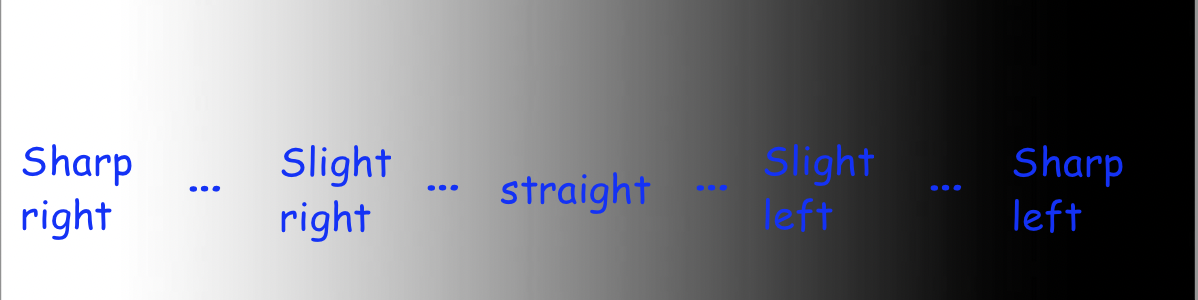
Instead of only having two cases, it seems like we’d want a whole bunch of cases, for anywhere from a sharp left turn to going perfectly straight to a sharp right turn, and everything in between, based on whether the reflectance sensor is completely on white, grey, black, or somewhere in between.
Having a long chain of if-else statements doesn’t sound fun. Perhaps we can look at this with a completely fresh approach?
From the previous module, we looked at proportional control to smoothly control the robot’s distance to the wall using the distance sensor. Can we use the same concept here?
Calculating error
With proportional control, we have an error value we desire for it to tend to zero, and some motor output is controlled proportional to the error to minimize that error - in the case of maintaining a certain distance to the wall, the error was the difference between the target and actual distance, and the output was the speed of both drive motors. In the case of line following, the error is the difference from 0.5 - since ideally, the robot follows the grey edge of the line and goes straight - and the motor output is how the robot should turn.
So, we can obtain error value with the following code:
error = reflectance.get_left() - 0.5
Above, we subtract 0.5 to normalize the reflectance value: the error is negative when the robot is too far left and needs to turn right, and positive when the robot is too far right and needs to turn left. Let’s put that code into the test. We can put it in the loop, print out the error at each iteration, and move the robot around the line to see how the error changes. The code is as follows:
while True:
    error = reflectance.get_left() - 0.5
    print("Error:", error)
    time.sleep(0.01)
Implementing proportional control
Based on the computed error, we want that to determine how much the robot turns.
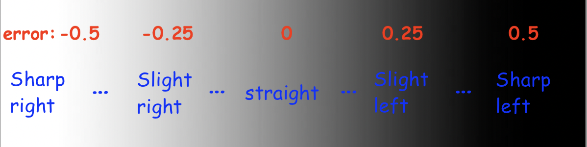
This image illustrates how the error impacts how much we want to turn. Remember: making the robot turn is simply setting the left and right motors to different speeds. So, the solution is to set a base speed - say, 0.5 - that both motors move at when the error is at 0. Then, have the calculated error influence the difference in speeds between the two motors. As explained through code:
drivetrain.set_effort(base_speed - KP*error, base_speed + KP*error)
This would be run inside the loop. The base_speed represents the average speed of the motors, no matter how much the robot turns. KP scales how much the robot should turn based on the error - a higher KP means the robot will react more violently to small deviations in error.
Let’s do a sanity check to make sure the code makes sense. We assume base_speed = 0.5 and KP = 1. If the reflectance reads whitish-grey and yields a value of around 0.25, the error would be -0.25, meaning that the left motor’s speed is 0.5 - 1*(-0.25) = 0.75, and the right motor’s speed is 0.5 + 1*(-0.25) = 0.25. Motor speeds of 0.75 and 0.25 would indicate a turn to the right, and the code does as desired.
This is a video illustrating line following with one-sensor control. Notice the smoother tracking compared to on/off control, yet the robot is still unable to recover from the last bend, because even a small amount of strafing from the line results in the robot completely losing where it is. Also, the KP value was not equal to 1 here; it’s up to you to figure out the best KP value for your bot.
INSERT Video
Mini Challenge: Proportional Line Follow
Write code for the robot to follow the line with proportional control, as shown in the video above. Note: this isn’t much more than calculating error as shown in the previous section then integrating the above line of code in a loop.
Play around with the value of KP. How does a higher or lower KP affect the amount of oscillation when following the line, and how responsive the robot is to curved lines? What is the optimal value of KP?